Extrusion helical gears
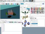
I recently just included Extrusion object into VRMath2 Editor and started to experiment its applications in creating 3D objects. It is quite easy to use Extrusion to create Spur Gears, but here I am showing how it can be used to created Helical Gears.
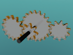
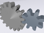
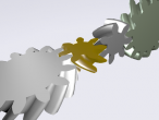
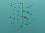
Extrusion starts with a crossSection, which is a 2D polygon shape on X-Z plane. It has a spine (usually along the Y axis direction) to define how many crossSections will be at certain 3D coordinates. Each spine coordinate has an associated scale (for resizing) and orirentation (for twisting) to create quite interesting extruded objects. The helical gear set below demonstrates the use of orientation to create the helical gears. Click on the big gear can toggle the animation.
Below are the Logo programs with some comments.
; Extrusion Helical Gears RESET SETBG 34 ; Global parameters for meshing gears ; http://www.gearseds.com/files/6.3.1_Gear_Terms_Lesson_rev3.pdf MAKE "pa 20 ; pressure angle, common angles are 14.5, 20 MAKE "dp 24 / 2.54 ; diametral pitch = tn / pd (in inch) ; below are derived from global parameters above MAKE "add 1 / :dp ; addendum MAKE "ddd 1.157 / :dp ; dedendum ; tn: number of teeth ; thickness: thickness of gear ; dir: helical direction. 0: left turn, 1 or other values: right turn ; angle: total helical angle ; clearance: not implemented in this prototype ; gear3d will output the parent transform id for the gear. TO helix :tn :thickness :dir :angle ; find four key diamater from outside to inside MAKE "od (:tn + 2) / :dp ; overall diameter of the gear = (tn+2)/dp MAKE "or :od / 2 ; overall radius MAKE "pd :tn / :dp ; pitch diameter MAKE "pr :pd / 2 ; pitch radius MAKE "bd :pd * COS :pa ; base diameter MAKE "br :bd / 2 ; base radius MAKE "rd (:tn - 2) / :dp ; root diameter MAKE "rr :rd / 2 ; root radius ; other derivitives MAKE "ta 360 / :tn ; angle between two teeth ; oc: outside circle ; pc: pitch circle ; bc: base circle ; rc: root circle MAKE "cs [] ; record initial pos and ori MAKE "pos POS MAKE "ori ORI ; ru 90 fd :thickness / 2 make "objCenter pos bk :thickness / 2 rd 90 ; collect coordinates HOME DN :thickness/2 REPEAT :tn [ ; collect sequence center -> rc -> bc -> pc -> oc -> oc -> pc -> bc -> rc LT :ta/3.4 FD :rr QUEUE "cs XCOR QUEUE "cs ZCOR BK :rr RT :ta/3.4 LT :ta/3.6 FD :br QUEUE "cs XCOR QUEUE "cs ZCOR BK :br RT :ta/3.6 LT :ta/4 FD :pr QUEUE "cs XCOR QUEUE "cs ZCOR BK :pr RT :ta/4 LT :ta/14 FD :or QUEUE "cs XCOR QUEUE "cs ZCOR BK :or RT :ta/14 RT :ta/14 FD :or QUEUE "cs XCOR QUEUE "cs ZCOR BK :or LT :ta/14 RT :ta/4 FD :pr QUEUE "cs XCOR QUEUE "cs ZCOR BK :pr LT :ta/4 RT :ta/3.6 FD :br QUEUE "cs XCOR QUEUE "cs ZCOR BK :br LT :ta/3.6 RT :ta/3.4 FD :rr QUEUE "cs XCOR QUEUE "cs ZCOR BK :rr LT :ta/3.4 RT :ta ] LT :ta/3.4 FD :rr QUEUE "cs XCOR QUEUE "cs ZCOR BK :rr RT :ta/3.4 QUEUE "cs XCOR QUEUE "cs ZCOR ; collect spine HOME DN :thickness/2 MAKE "spine [] QUEUE "spine POS MAKE "orientation [] QUEUE "orientation ORI REPEAT 4 [ RU 90 FD :thickness/4 QUEUE "spine POS RD 90 IFELSE :dir = 0 [ LT :angle/4 ] [ RT :angle/4 ] QUEUE "orientation ORI ] MAKE "scale [ 1 1 ] ; make parent transform HOME TRANSFORM SET OBJECT "translation :pos SET OBJECT "rotation :ori SETPARENT OBJECT TRANSFORM SETPARENT OBJECT MAKE "paobj OBJECT EXTRUSION MAKE "obj WORD OBJECT "_extrusion SET :obj "crossSection :cs SET :obj "spine :spine SET :obj "scale :scale SET :obj "orientation :orientation SET :obj "convex "false SET :obj "creaseAngle 1.57 SETSCALE .2 3 .2 SETMAT 3 32 BOX SETSCALE 1 1 1 SETPARENT "root SETPOS :pos SETHEADING :ori OUTPUT :paobj END TO getPR :tn OUTPUT :tn / :dp / 2 ; output pitch radius END CLEAN HOME MAKE "g1n 24 MAKE "g2n 12 MAKE "g3n 12 RU 90 SETMAT 3 6 MAKE "gear1 helix :g1n .5 0 22.5 RT 90 FD getPR :g1n FD getPR :g2n LT 90 RT 180/:g2n SETMAT 3 34 MAKE "gear2 helix :g2n .5 1 45 HOME RU 90 FD getPR :g1n FD getPR :g3n TL 90 RT 360/:g3n SETMAT 3 34 MAKE "gear3 helix :g3n .5 0 45 ; spin gears SPIN :gear1 "rt 60 SPIN :gear2 "lt 60 / (:g1n/:g2n) SPIN :gear3 "lt 60 / (:g1n/:g3n) ; create some actions TOGGLE "act1 WORD "spin_ts_ :gear1 "enabled TOGGLE "act2 WORD "spin_ts_ :gear2 "enabled TOGGLE "act3 WORD "spin_ts_ :gear3 "enabled ; obj_2 is the 24-teeth gear CLICK "obj_2 "act1 CLICK "obj_2 "act2 CLICK "obj_2 "act3
There are some strange behavious found when I use extrusion. For example, it is best to create extrusion at the coordinate 0,0,0. Or the orientation of extrusion will behave strangely.
I think extrusion can also be used to generate Bavel Gears and other types of gears. And I can create better tree trunk for my palm tree project.
Files: extrusion_helical_gears.x3d extrusion_helical_gear.logo
- Andy's blog
- Login or register to post comments
- 5445 reads
Comments
nice
Very nice, this is a great addition even if Extrusion in x3dom may not be 100% supported. Extrusion maps well to the egocentric turtle control and will make it much easier to create 3d, volumetric objects. It also leaves all the meshing to x3dom.
Why do you think you need an :angle of 22.5 for the large gear but 45 for the small gears ? I cannot figure out the reason.
Using Extrusion for the involute gears will make both the logo and the x3d much more compact.
angles
Using 45 degrees (for small gears) is a convinient guess for the 90 degree meshing gear. The angle 45 is then used as the total rotation (orientation) of the extrsution. The big gear has double number of teeth (so as the diameters, circumference) so its total rotation of extrusion is halved (inverse proportional, considering the gear ratio and rotation speed) in order to mesh. However, this only works for side by side helical gears. For the 90 degrees meshing, the inverse proportional relationship does not work, and I have not worked out their relationship. Any maths suggestions?
I have also tried using extrusion for bavel gear, but could not meshing them... Need to read more about gears.
depth
It turns out that the helical angle is not the angle by which the back face of the gear is rotated with respect to the front face. This total rotation angle in radians is tan(h) * depth / r where h is the helical angle, depth is the depth of the gear and r is the pitch radius. This can be derived by looking at the triangle which is formed the front, back and trace of a tooth.
I converted my involute gears to extrusions which speeds up the creation and rendering process a lot and made the code much more streamlined. It is now feasible to produce many nice gears in a single scene. However, begin and endcaps do not work in many but not all cases. So I will have to go back to manually adding in the back and front polygons, unfortunately. I will produce a new blog when this is ready.