


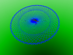


involute gear


It turned out that producing a set of involute gears requires quite a bit of geometry in addition to involutes.
It is useful to get familiar with gear terminology and with the special properties of an involute of a circle. In particular, it is necessary to figure the angular width of a tooth at the base circle which is where the involute, curved section of a tooth begins.
So there is a lot to explain in this logo program.
Next steps include to figure out why there is a slight overlap between teeth from both gears, and to make the gears 3d with some depth. Is there a way to use the extrusion functionality of x3d ?
[Update: the initial configuration was slightly off. Scene and logo updated.]
Well, here is the logo:
- aplesch's blog
- Login or register to post comments
- 30136 reads


Comments
update: better fit
After some careful examination of the initial position of the two gears, it became clear that they were slightly off, even before spinning. It was necessary to rotate both gears a bit such that the radii from the pitch circles align. Since the initial drawing starts at the base radius rather than the pitch radius this meant a rotation by the angle between base and pitch radii (beta above).
Now, there is almost no overlap. However, while most teeth mesh nicely, some still have some overlap. This may be mostly due numerical imprecision which tend to accumulate due to the way the gear is drawn. Each new tooth is drawn relative to the location and orientation of the previous tooth. Also there is a finite precision to the involute curve.
While the overlap is only noticeable when zoomed in at the location of contact, it might be nice as a workaround to just separate the two gears a bit more than strictly necessary.
Rotation & overlap
I experienced some rotation problems in my gear3d but kind of solved with a customed keyvalues. See my new blog at https://vrmath2.net/content/spur-gears
The overlap seems to occur with fewer teeth gears. Other solutions may be including a clearance or an unercut.
Undercut
I also remember reading about smaller gears with fewer teeth requiring additional accommodation space for the partner. Something for the future.
x3d DEF/USE
The x3d file is pretty large in part because all teeth are explicitly defined. Is there a way to use the DEF/USE mechanism of x3d ? I would like to just define one tooth and then reuse it by reference.
Copy & paste
I have commands COPY and PASTE, which result in DEF/USE. However, it only USE the Shape node. You can run the codes below and check the x3d codes for details.
Another thought about the large size could be the total of some hundreds objects. It would be smaller if just one IndexedLineSet for one gear. And if in the future we need to extrude the gear, the 2D coordinates (x and y) will need to be collected..
def/use
Thanks. I tried copy and paste but only with transform object which did not seem to work. I guess I need to figure how to collect points in order and then use just one line or copy and paste. Would it be possible to support copy and paste for a transform object as well ?
Thanks for allowing updates to roations in the property inspector !
The XML export seems more standard and the meta tags in the header are really nice as well !
DEF/USE
I did have DEF/USE for transform node before but remembered to have some issues, and need to try again. Perhaps I can have a second input for COPY to indicate transform or shape....
Collecting
Collecting turtle positions in a growing list was quite possible after discovering that
Somehow behaves differently than the explicit
More in an update.
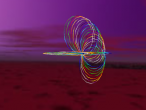
3D gears
You are quick to update with 3D version of involute gears.. They look very nice and smooth...
The OUTPUT command is like the return in javascript. I use it to return a thing after calling a procedure. My new Spur Gear example (https://vrmath2.net/content/spur-gears) has it too, or this one https://vrmath2.net/content/3d-function-elevationgrid
Using native LIST and the PUSH or QUEUE commands can easily collect data such as position and orientation. They can be later used to create animation or tour. They are orginal Logo commands, see https://vrmath2.net/content/logo-guidereference#sec2
I think that Logo can be very good at collecting 3D data. I planned to implement a Data Collector GUI in VRMath2 Editor but have not got time to do so. Some data collection commands are already implemented, see https://vrmath2.net/content/logo-guidereference#sec6_15 for commands COLLECTPOSITION, COLLECTORIENTATION and COLLECTVIEW etc. The Data Collector will aim to assit data collection and form the Logo codes for use in the Logo Editor.
Cool involute gear
With these handy procedures (not easy to create...), we can generate gears with any number of teeth. I think the angles are pretty good. The slight overlap may due to the beginning gear rotation as there seem to have a gap on one side, and slightly overlap on the other side.
The SPIN was used with gear ratio? Their rotation periods allow teeth to gear in well.
I tried to include extrusion long time ago but at the time, it was experimental. I am surprised to find it has been fully implemented.. It may be time to include extrusion into VRMath2. It would be a nice way to make the gear 3D.
You may have noticed that I changed the X3D publish. Recently, I was trying MeshLab and Blender to convert my x3d files generated in VRMath2 to STL and/or PLY so they can be printed in 3D printers. I found that MeshLab and Blender only take XML encoded x3d files. Therefore I have changed in VRMath2 to output stnadard X3D files in XML format. It may take a little bit more time to publish but worth it because MeshLab and Blender did convert X3D to STL and PLY. The problem is that they seem to only convert IndexedFaceSet, IndexedLineSet and maybe PointSet. They don't take in other 3D primitives such as Box or Extrusion...