helical gears
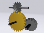
The real advantage of gear modelling in 3d is that gears in a mesh do not have to parallel each other. It is posible to demonstrate how gears can transfer rotation (and forces) to orientations other than the driving gear. This kind of transfer is possible by use of helical gears.
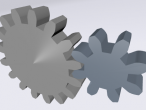
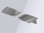
Helical gears have their teeth at an angle to the axis of the gear but are otherwise very similar to spur gears. In fact, profiles through a helical gear are all identical and rotated by an amount proportional to their distance from the front.
Based on the 3d involute gears program, helical gears therefore did not require too many changes. The main idea is that instead of just extruding the gear profile in one step, now several quads in the direction of the helical angle are generated, with the correct amount on distorttion (rotation) based on the width of each segment.
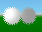
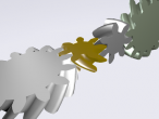
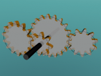
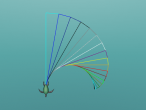
Here is the logo which is quite similar to the 3d involute gear logo but has the rotated extrusion and some smaller changes including the addition of a third gear. It takes quite a long time to run.
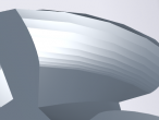
The triangles across the teeth were qute noticable. Changing the crease angle by editing the x3d helped.
; involute: draw involute ; rb: base radius ; limit: max. generating angle ; steps: number of segments on involute to draw ; returns list of positions: top is first TO involute :rb :limit :steps LOCALMAKE "start POS LOCALMAKE "i 0 LOCALMAKE "step 0.5 * :limit / :steps LOCALMAKE "coords [] PUSH "coords POS PU REPEAT ABS(:steps) [ ;push "coords :start MAKE "i :i + :step ;move along circle LT :step FD 2 * :rb * SIN :step ;find tangent RT 180 - :step ;unroll string FD 2 * :i * :deg2rad * :rb ;make "start pos ;record position PUSH "coords POS BACK 2 * :i * :deg2rad * :rb ;turn forward LT 180 ] SETPOS :start OUTPUT THING "coords END ; gearinvolute: draw involute side of gear tooth ; rb: base radius ; PA: pressure angle ; P: diametral pitch ; steps: number of subdivisions ; returns list of position from landing to base TO gearinvolute :rb :PA :P :steps LOCALMAKE "a 1 / :P LOCALMAKE "ro ( :rb / COS :PA ) + :a ;calculate generating angle for top of tooth ;(needs drawing) LOCALMAKE "l2 :ro ^ 2 - :rb ^ 2 LOCALMAKE "limit ( SQRT :l2 ) / :rb LOCALMAKE "coords involute :rb (:limit / :deg2rad) :steps OUTPUT THING "coords END ; geartooth: draw one full tooth ; rp: radius of pitch circle ; PA: pressure angle ; P: diametral pitch ; hdelta: half angular base width (expected) ; segments: number of subdivisions on each side ; returns list of positions from root to landing to root TO geartooth :rp :PA :P :hdelta :segments LOCALMAKE "rb :rp * COS :PA LOCALMAKE "clr (2.157 - 2) / :P ;coarser 20P LOCALMAKE "ddif (1/:P + :clr) - (:rp - :rb) LOCALMAKE "coords [] PUSH "coords POS ; record straight edge RT 90 FD :ddif PUSH "coords POS LT 90 ; save position LOCALMAKE "base POS LOCALMAKE "head HEADING ; record side MAKE "coords SENTENCE ( gearinvolute :rb :PA :P :segments ) :coords ;record with negative step LOCALMAKE "top POS SETPOS :base SETHEADING :head ;turn and move to other side of tooth ;half angular base width LT :hdelta FD 2 * :rb * ( SIN ( :hdelta ) ) LT :delta / 2 ;save pos MAKE "base POS MAKE "head HEADING ;draw other side ;prepend reverse MAKE "coords SENTENCE REVERSE ( gearinvolute :rb :PA :P :segments * -1 ) :coords ;return to base SETPOS :base SETHEADING :head ;record straight edge LT 90 FD :ddif PUSH "coords POS RT 90 OUTPUT THING "coords END ; gear: draw involute gear ; rp: radius at pitch circle ; PA: pressure angle ; P: number of teeth normalized by pitch diameter ; segments: subdivions on each involute side of each tooth ; returns list of positions TO gear :rp :PA :P :segments LOCALMAKE "cpitch :PI / :P LOCALMAKE "apitch (:cpitch / :rp) / :deg2rad LOCALMAKE "N :P * :rp * 2 LOCALMAKE "rb :rp * COS :PA LOCALMAKE "clr (2.157 - 2) / :P ;coarser 20P LOCALMAKE "ded (1/:P + :clr) LOCALMAKE "rr :rp - :ded ;this is the main calculation ;for angular base width delta ;(needs drawing) LOCALMAKE "alpha ( TAN :prA ) / :deg2rad LOCALMAKE "beta :alpha - :prA LOCALMAKE "delta ( 0.5 * :apitch ) + ( 2 * :beta ) LOCALMAKE "coords [] ; move from center to root PU RT 90 FD :rr LT 90 REPEAT :N [ ;tooth from root to root MAKE "coords FPUT ( geartooth :rp :PA :P :delta / 2 :segments ) :coords ;advance to root of next tooth LT (:apitch - :delta) / 2 FD 2 * :rr * SIN ((:apitch - :delta) / 2) LT (:apitch - :delta) / 2 ] ;close up ;push "coords pos LT 90 FD :rr RT 90 OUTPUT THING "coords END TO polygon :positions JUMPPOS FIRST :positions FOREACH "setpos BF :positions END TO firstlast :positions OUTPUT LIST FIRST :positions LAST :positions END TO plate :positions PU SETPOS FIRST FIRST :positions FACE PCOFF PD FOREACH "polygon :positions ;fill circle polygon REDUCE "sentence MAP "firstlast :positions ;show reduce "skinny :flatpositions PU LINE OUTPUT OBJECT END TO skinny :p1 :p2 JUMPPOS :p1 SETPOS :p2 SETPOS :pcenter OUTPUT :p2 END TO gear3d :positions :width :helix :radius :fsegments LOCALMAKE "posflat FPUT (LAST LAST :positions) (REDUCE "sentence :positions) fence :posflat :width ; does not seem to work ;set object "creaseAngle 1.57 COPY plate :positions SET OBJECT "rotation [0 0 1 0] PASTE ;object not updated after paste LOCALMAKE "pasted WORD "obj_ (REDUCE "word BF BF BF BF OBJECT) + 1 SET :pasted "rotation (LIST 0 0 1 (TAN :helix) * :width / :radius) SET :pasted "translation ( LIST 0 0 :width ) END TO fence :positions :width PU SETPOS FIRST :positions FACE PCOFF PD SHOW REDUCE "quads :positions PU LINE END TO quads :p1 :p2 LOCALMAKE "p22 :p2 LOCAL "p3 LOCAL "p4 ;fsegments inherited from gear3d REPEAT :fsegments [ JUMPPOS :p1 SETPOS :p2 MAKE "p3 offsetz :p2 :width / :fsegments MAKE "p4 offsetz :p1 :width / :fsegments SETPOS :p3 SETPOS :p4 MAKE "p1 :p4 MAKE "p2 :p3 ] OUTPUT :p22 END TO offsetz :point :offset LOCALMAKE "x FIRST :point LOCALMAKE "y FIRST BF :point LOCALMAKE "z LAST :point LOCALMAKE "rad SQRT (:x ^ 2) + (:y ^ 2) ;helix and radius inherited from gear3d LOCALMAKE "rot (ARCTAN :x :y) + (TAN :helix) * :offset / :radius / :deg2rad OUTPUT (LIST (:rad * COS :rot) (:rad * SIN :rot) :z + :offset) END ;involute (for gears) ;comprehensive guide ;http://bostongear.com/pdf/gear_theory.pdf RESET CLEARSCREEN SETBACKGROUND 34 POINTLIGHT RU 90 MAKE "PI 4 * RADARCTAN(1) MAKE "deg2rad :PI / 180 MAKE "prA 14.5 MAKE "piR 0.5 MAKE "piR2 0.25 MAKE "pitch 24 MAKE "facesegments 4 MAKE "gear1center POS MAKE "gear1line gear :piR :prA :pitch 10 MAKE "gear2line gear :piR2 :prA :pitch 10 RT 90 FD :piR + :piR2 + :piR2/20 ;some slack LT 90 MAKE "gear2center POS SETPOS :gear1center TRANSFORM MAKE "gear1spin OBJECT SET :gear1spin "rotation [0 0 1 0] SET :gear1spin "center :gear1center SETPARENT :gear1spin TRANSFORM MAKE "gear1 OBJECT SET :gear1 "rotation [0 0 1 0] SET :gear1 "center :gear1center SETPARENT :gear1 SETMATERIAL 3 33 gear3d :gear1line -0.2 45 :piR :facesegments SETPARENT "root TRANSFORM MAKE "gear2spin OBJECT SET :gear2spin "rotation [0 0 1 0] SET :gear2spin "center :gear1center SET :gear2spin "translation :gear2center SETPARENT :gear2spin TRANSFORM MAKE "gear2 OBJECT SET :gear2 "rotation [0 0 1 0] SET :gear2 "center :gear1center ;set :gear2 "translation :gear1center SETPARENT :gear2 SETMATERIAL 3 28 gear3d :gear2line -0.2 -45 :piR2 :facesegments SETPARENT "root TRANSFORM MAKE "gear3rot OBJECT SET :gear3rot "rotation [0 1 0 1.57] SET :gear3rot "center :gear1center SET :gear3rot "translation (LIST 0.1 (:piR + :piR2) -0.1) SETPARENT :gear3rot TRANSFORM MAKE "gear3spin OBJECT SET :gear3spin "rotation [0 0 1 0] SET :gear3spin "center :gear1center SET :gear3spin "translation :gear1center SETPARENT :gear3spin TRANSFORM MAKE "gear3 OBJECT SET :gear3 "rotation [0 1 0 0] SET :gear3 "center :gear1center ;set :gear2 "translation :gear1center SETPARENT :gear3 SETMATERIAL 3 28 gear3d :gear2line -0.2 45 :piR2 :facesegments SETPARENT "root MAKE "beta (TAN :prA) - (:prA * :deg2rad) ;inital rotations SET :gear1 "rotation (LIST 0 0 1 -:beta) SET :gear2 "rotation (LIST 0 0 1 :PI/:pitch/:piR2 - :beta) SET :gear3 "rotation (LIST 0 0 1 :PI/:pitch/:piR2/2 - :beta) MAKE "period1 60 SPIN :gear1spin "tl :period1 SPIN :gear2spin "tr :period1 * :piR2/:piR SPIN :gear3spin "tl :period1 * :piR2/:piR PU SHOWALL
This update take advantage of how scope works in logo, eg. that variables are available to subprocedures.
- aplesch's blog
- Login or register to post comments
- 16661 reads
Comments
x3d players
OK, the generated x3d almost work with external x3d players like octaga or freewrl. Some changes were necessary:
- add DEF fields in addition to id fields. DEF needs to be in capitals (!)
- ROUTE in caps.
The validator in x3d edit had lots of complaints.
x3d casesensitivity
This should be easy to fix... I suppose the USE needs to be in capital too?? Thanks for finding this issue.
fixed
I have fixed the x3d export and now it will have capital USE, DEF, and ROUTE.
For copy and paste, so far it only works on shape. I am still thinking about your copygeometry idea...
Or maybe I should just use DEF and USE as the commands to do on any node..
case sensitivity
A couple of other x3d names which could be revised are:
bboxcenter -> bboxCenter
bboxsize -> bboxSize
Timesensor -> TimeSensor
"1,1,1" -> "1 1 1" (commas only between triplets)
Bravo helical gears
Wow I want to learn how to do it... (I am almost done marking).. I think this helical gear can be exported and 3D printed as well...
The creaseAngle is something I haven't looked at. Last time (some months ago) I did not seem to see it in the DOM.
I wonder how is done by EXTRUSION when I implemented it....I should try a manual x3d first..
I saw you used local variables. Do they stay after the procedure finished?
scope
I had an idea that it may be possible to create helical gears from the spur gears. The main idea is to rotate each profile through the gear by an amount determined by the helical angle and its distance from the front profile. The amount of rotation is tan (helical angle) * distance / pitch radius in radians. Instead of rotating each profile I rotate each segment on the profile and connect them to a twisted quadrangle.
For printing one should increase the number of fsegments (profiles) to as high as possible (10?). It will take a long time to generate a gear and the x3d will be large. Since all coordinates for a gear are on one line in the x3d I hope the resulting line length is still ok for x3dom or browsers.
Not sure how to do this with EXTRUSION since the extruded profile stays perpendicular to the path of extrusion, I believe.
Local variables are local to the procedure where they are defined (as are the inputs) but stay for all (sub)procedures which are called from the procedure. When the procedure in which they were defined finished they disappear and one does not have to worry if the name of the variable is used again for something else.
twisted
IndexedFaceSets are supposed to have only planar polygons, not twisted ones as I have defined:
http://www.web3d.org/documents/specifications/19775-1/V3.3/Part01/compon...
I think this is reason why there is a discrete (not smooth) boundary between each quadrangle even with a crease angle. I may change the quads procedure to generate ccw triangles instead of quads. Unfortunately this will make the x3d file size even larger (from four coords and one -1 to 6 coords and two -1) . Also I should rename the offsetz procedure but I cannot think of a good name.
I tried the x3d with octaga player and freewrl and both show the gears but do not animate. Perhaps the routes are in the wrong place for them, not sure. But ROUTE statements can occur anywhere. Perhaps they want ROUTE in all caps.
Coordinates duplicated
Another reason why there is no smoothing is that coordinates are duplicated where instead they could be shared. But this is how face mode is designed. When the turtle goes back to a point which is also used by another polygon it will create a duplicated coordinate for the x3d because logo cannot know that. Perhaps there is a way to manipulate the iindices though this sounds complicated ?
Problem long ago
You found my problem so quickly. It is a happy feeling that someone knows my work.
I tried to solve the creaseAngle problem (duplicated coordinates) when I did the Mobius ring https://vrmath2.net/content/infinite-mobius-space
It is not easy (not sure if any algorithm) for the turtle to check which coordinates have been recorded during the movements. I was thinking of a post PU reduction function to detect duplicated coordinates and modify the index accordingly, but that is not an easy job either.. would you be able to help with writing such as function?
shared vertices
Is it possible to access the coordIndex field with the set command ? If it is, first my plan was to do what you suggested, in logo. A procedure which would copy the list of coordinates, remove duplicates, and then adjust the indices accordingly.
Then, for my particular case, I thought it would be easier and faster, to just deal with the 'fence' ('extrusion') and for each segment reassign the first two indices to the last two indices of the previous quad since the position in the list and the values are all known.
So I would like to try this first. But that would only work if coordIndex can be modified by set.
In javascript it also should be possible to do some thoughtful array manipulation to optimize the coords and coordIndex arrays, after PU. Somehow, I think it would make sense to use an associative array with coord triplets as (string) indices and the indices as values.