


X3D: behind-the-scenes


Here is a look at the 3d technology which drives vrmath behind the scenes. It is called X3D and has its own web site. Understanding this technology not only helps in how vrmath extends turtle graphics into 3d but opens the door to a large world of virtual reality in general (x3dom, web3d). It turns out that the vrmath editor is itself a good tool to get to know X3D. Here is how.
Let's produce a simple scene in the editor (follow Create), and look at the X3D code. The instructions use the menu bar at the top.
Insert - Shape - Cube : This will place a box at the center of the world.
File - Publish Word - View Codes (lower left): The opened window contains a complete X3D description of the world. You can now use that X3D description in any software which supports the X3D standard. Here is an example:
Select all X3D code from the window and copy it to the clipboard. Then open a new browser tab here: http://andreasplesch.github.io/Library/Viewer/x3dom.html and paste the X3D code into the input area. Click "Update" and you will see the scene in te scene below it. Notice how the background is still white and not blue as it is in the vrmath editor. Let's fix the background.
Close the X3D code window in the vrmath editor.
Toggle on "Include current Background" and click "View Codes" again. Now the X3D code has an additional line starting with <Background which defines the background of the scene. Copy and paste over the code to the other browser tab and click "Update" again. Now the background in this tab is also blue. Back in vrmath, try to toggle on other settings in the "Publish Setting" window and observe how the X3D code reflects the settings.
Other lines in the X3D code also correspond to elements in vrmath. For example, <Scene> represent the start of a world, and <Box the inserted cube. We can use the vrmath editor to manipulate the X3D elements.
Close the "Publish Setting" window.
Find the "Object Tree" window and click on "TRANSFORM obj_0". This selects the cube. See if you can find the corresponding <Transform .. line in the X3D code (it should be still available in the other browser tab).
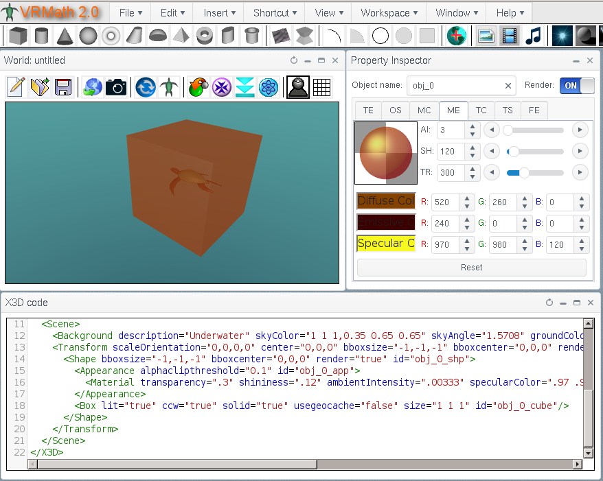
To see how the cube is defined within "TRANSFORM obj_0", find the "Property Inspector" window and click on the "OS" (Object Setting) tab. Note how in the Property Inspector window the object name is "obj_0" and the object is recognized as Cube (with the name "obj_0_cube").
In the "OS" tab there are five attributes for the Cube: "size" to "lit". These attributes correspond to the attributes in the <Box .. line of the X3D code. You can actually edit these attributes right in the Property Inspector.
Edit the "size" attribute to:"1 1 2" and click Update. The cube changes its size. Now the edge along the Z coordinate is longer.
Use File - Publish Word - View Codes to see how the <Box line now has a size="1 1 2" attribute.
Close the "Publish Setting" window.
Back in the "Property Inspector" now click on the "MC" (Material Chooser) tab. Click on a color and the box will immediately change its color accordingly.
Then click on the "ME" (Material Editor) tab. The color shown here is the one you picked in the "MC" tab. The "MC" tab just has (a lot of) predefined and grouped colors. In the "ME" tab you can see that the "color" is actually a product of six different attributes. So it is called a "material". Let's look again at the X3D code to find this material.
Use File - Publish Word - View Codes and look for the <Material ... line. Its attributes from transparency to diffuseColor correspond to settings in the "ME" tab. The "ME" tab shows the same values but multiplied by a 1000.
In the X3D code you can see that there is an <Appearance line which contains the <Material line. The Appearance node is automatically generated by vrmath. Since it does not have important attributes it is not possible to edit from vrmath. You can also see that there is a <Shape line which is also automatically generated. The Shape node associated the Appearance and Material with the Box geometry. It is also does not have important attributes and cannot be edited.
Finally, let's look at Transform.
Close the "Publish Setting" window.
Back in the "Property Inspector" click on the "TE" (Transform Editor). Find the Translation input and use the little triangles next to the Z: input to change the Z component of translation. The box will move along its long axis accordingly.
Again, looking at File - Publish Word - View Codes will show that all the attributes in the "TE" tab are reflected in the <Transform line which has the same attributes. You may notice how some numbers are separated by spaces and some by commas. It does not matter.
In the X3D code the Transform node contains the Shape node. This means that the Shape node is affected by the translation etc. defined by the Transform node.
There are many other X3D nodes and attributes which vrmath makes easy to add and manipulate in a scene. You may also try to directly edit the X3D code in the x3dom viewer tab to see the effects of your edits.
Hopefully, this short introduction provides some background on the X3D technology used by vrmath. You can learn more here.
- aplesch's blog
- Login or register to post comments
- 6450 reads