


Tutorial page


VRMath Tutorial Page
[3D Logo] [Logo command] [Logo procedure] [Project management] [Logo links]
This page gives a brief introduction on the Logo language used in VRMath. You will get a general idea about how to use commands and write procedures. You can also learn how to save your project at the end of this tutorial.
See also: Command Library, VRMath Interface Tour, Programming Interface.
3D Logo
Logo language has had long history, profound research literature and resources (see Logo links). VRMath is an integrated VRLE (Virtual Reality Learning Environment) or microworld, in which the Logo language is an important component of the three (see Interface Tour and Research Papers). However, the Logo language in VRMath is not just another dialect or extension of Logo. It is a very distinctive Logo that has never been seen before -- it is a 3D Logo.
Because of the 3D real time graphics (VR) in VRMath, the Logo language here has significant conceptual changes. For examples:
- Traditional 2D Logo has a 2D graphical window, the turtle is bound in a square window. When turtle moves out of the boundary, you have to specify the WRAP command or use scroll bars to scroll the window. The 2D square is limitedly small. While in VRMath, the VR graphical interface is an almost infinite 3D space that allows users to walk, fly, or examine in the 3D virtual space.
- Traditional 2D Logo uses pixels as the unit of distance. While in VRMath, the unit of distance is meter or centimeter as we use in the real world.
- Traditional 2D Logo has two turns only (left and right). While in VRMath, the 3D space requires six turns (left and right, rollup and rolldown, tileleft and tileright). The 2D Logo has limitations for the research on human's 3D spatial ability, while VRMath has the potential to investigate on human's full range of 3D spatial ability.
- Traditional 2D Logo is drawing pixels on screen, while VRMath is creating dynamic objects in 3D space, which can perform behaviours (animation) to reflect the real world. (This feature hasn't been completely implemented)
As a result, the Logo language in VRMath has a set of 3D related commands, and has eliminated some unnecessary 2D commands. Generally speaking, to use VRMath, one has to change the pre occupied 2D concepts and imagine oneself is in a 3D world just like in the world we are living in.
Read on the following sections will orientate you to get into VRMath's 3D Logo quickly!
top
Logo command
You can specify commands in procedures or in the command input box as shown below.

Make sure the input field has got the input focus by mouse clicking in it before you type any commands.
The rule of Logo command syntax is easy. A command may or may not have parameters. If a command has parameters, you just leave a space between them. For example, you type in
METER [Enter]
tells the turtle that the unit of distance is now meters. Then type in
FORWARD 1 [Enter]
means to ask the turtle to move forward 1 meter. Here the 1 is the parameter of FORWARD command. You can also have variables or mathematical operations in the parameter, such as
FORWARD 1+2*3 [Enter]
means to ask the turtle to move forward 7 meters.
A semicolon in the beginning of command means the texts after the semicolon are comments only, not to be executed. You can also specify several commands in one line. All commands are not case sensitive. For example:
CM forward 200 BK 50 ; these commands mean to use centimeter unit, and the turtle moves forward 200 centimeter then backs 50 centimeter.
Now you are ready to know more commands. Please select one category of command below, or just carry on reading.
[Moving commands] [Turing commands] [Creating commands] [Colouring commands] [Material commands] [Font commands] [Setting commands] [Logo variables] [Mathematical operations] [Other commands]
Moving commands
The moving commands can change turtle's position in 3D space. Moving commands won't change the turtle's orientation. Basically, there are three sets of moving commands based on three frames of reference system.
-
Egocentric: This set of commands are based on turtle's viewpoint. They are:
FD or FORWARD
BK or BACK or BACKWARD
For example,
FD 3 BK 2 will make the turtle move 3 units forward then back 2 units.
-
Fixed: This set of commands are based on something or directions that are fixed and not to be changed. They are:
UP : The turtle goes up towards sky.
DOWN or DN : The turtle goes down towards ground.
EAST : The turtle goes towards east.
WEST : The turtle goes towards west.
NORTH : The turtle goes towards north.
SOUTH : The turtle goes towards south.
For example,
UP 1 EAST 2 NORTH 2
Note: You can turn on the compass by clicking on icon . By looking at the compass and the background, you should be able to tell these fixed directions.
-
Coordinate: This set of commands are based on the Cartesian coordinate system adopted in VRMath. The image below shows the three axis in 3D:

Some commands are: SETPOS, SETXYZ, SETX, SETY, SETZ... etc.
For example,
SETXYZ 1 2 -1 will move the turtle to position (1,2,-1).
Note: the moving parameters are all affected by METER and CM commands.
There is also a set of jump commands associated with every moving command. You can just add "JUMP" before every moving command. For examples, JUMPFORWARD or JF, JUMPBACK or JB, JUMPEAST or JE, JUMPUP or JU, JUMPXYZ or JXYZ, JUMPX or JX etc. This JUMP series commands act the same when you just move the turtle. But they will have effect when you are creating turtle tracks objects (PENDOWN or PD). For example, JUMP series commands mean temporarily no tracks, or end of a face.
For more moving commands, please refer to Command Library page.
Turing commands
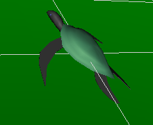
The turning commands will not change the turtle's position, but change its orientation (or rotate the turtle). There are six turning commands, each have a degree parameter:
LEFT or LT : the turtle turns left.
RIGHT or RT : the turtle turns right.
ROLLUP or RU : the turtle's head up.
ROLLDOWN or RD : the turtle's head down.
TILTLEFT or TL : the turtle's left side down and right side up.
TILTRIGHT or TR : the turtle's left side up and right side down.
For example,
Here is the turtle's original orientation.
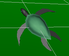
After LT 45 ; left 45 degree
then RU 30 ; roll up 30 degree
then TL 45 ; tilt left 45 degree

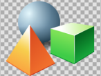
Creating commands
This set of commands creates geometric objects in 3D space. Objects are created according to turtle's position and orientation. These commands include:
PENDOWN or PD : Start recording turtle's track for point set, line set, or face set.
PENUP or PU : End of recording turtle's track.Note: One PD and PU creates one object. Use FACE, LINE, or POINT command before PD to determine the object type. There is a PENERASE or PE command for undo once when creating a PD object.
BOX or CUBE : Create a box object.
CAN or CYLINDER : Create a cylinder object.
CONE : Create a cone object.
BALL or SPHERE : Create a sphere object., and
LABEL : Create a label object. Only this command in this set needs a parameter.
For example,
LABEL "HelloWorld ; or
LABEL [I Love VRMath] ; for a sentenceNote: More options and commands for LABEL command can be found in Font Chooser in Tool menu, or see Font commands.
Point set and line set objects created by PD will be affected by pen color. You can use Pen Color Editor in Tool menu or pen color related commands to change pen color.
Face set object created by PD may be affected by pen color when PENCOLORON or PCON command is specified, or by material settings when PENCOLOROFF or PCOFF command is specified. You can change material settings by using Material Editor in Tool menu or material related commands.
All other objects will be affected by material settings.
All objects will be affected by SCALE series commands, which can be found in Setting commands.
Colouring commands
This set of commands can change the pen color for turtle tracks. Some commonly used commands are:
SETPENCOLOR or SETPC : This command has 1 parameter, which can be a number between 0 and 69 representing the color in the palette in Pen Color Editor. Or it can be a LogoList enclosed by [] containing 3 integer elements as red, green, and blue. Each color element ranges between 0 to 1000. For examples,
SETPC 4 ; Pen color is now the forth color in Pen color editor, which is white.
SETPC [1000 1000 0] ; Pen color is now yellow.Note: SETPC command can also be used with PALETTE series commands.
SETRGB : This command has 3 parameters as red, green, and blue. The three color elements range from 0 to 1000. For example,
SETRGB 1000 0 1000 ; Pen color is now purple. Note: There are also SETR, SETG, and SETB commands for each color element.
NEXTCOLOR or NC : This command has no parameter. It moves the pen color to the next color in the palette in Pen Color Editor. The COLOR command returns the current index of pen color.
Material commands
There are six elements in 3D objects material as described in Material Editor. Each element has one associated command:
SETDIFFUSECOLOR or SETDC : set diffuse color of object.
SETEMISSIVECOLOR or SETEC : set emissive color of object.
SETSPECULARCOLOR or SETSC : set specular color of object.each of the above 3 commands has 3 parameters: red, green, and blue ranging from 0 to 1000 in integer. For example,
SETDC 0 0 1000 ; set diffuse color to blue. Note: You can see the significant effect of diffuse color when headlight is on, or see the emissive color effect when headlight is off.
Another 3 commands are:
SETAMBIENTINTENSITY or SETAI : set ambient intensity for object.
SETSHININESS or SETSH : set shininess for object.
SETTRANSPARENCY or SETTR : set transparency for object.each of the above 3 commands has one integer parameter ranging from 0 to 1000. For example,
SETTR 500 ; set object to half transparent.
Note: Please use Material Editor in Tool menu for more information on the six elements.
Font commands
This set of commands are for LABEL command only. There are six of them, each has one parameter:
SETFONTFAMILY or SETFF : Three font families can be used in parameter: "SERIF, "SANS, and "TYPEWRITER.
SETFONTJUSTIFY or SETFJ : Four font justifies can be used in parameter: "FIRST, "BEGIN, "MIDDLE, and "END.
SETFONTSTYLE or SETFS : Four font styles can be used in parameter: "PLAIN, "BOLD, "ITALIC, and "BOLDITALIC.
SETFONTHORIZONTAL or SETFH : Set font horizontal. Use TRUE or FALSE as the parameter.
SETFONTLEFTTORIGHT or SETFL : Set font from left to right. Use TRUE or FALSE as the parameter.
SETFONTTOPTOBOTTOM or SETFT : Set font from top to bottom. Use TRUE or FALSE as the parameter.
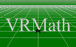
For example,
SETFJ "middle LABEL "VRMath ; the turtle's position is the middle for the label VRMath.
Setting commands
This set of commands influences the numbers used by moving commands or the object's content or type.
CENTIMETER or CM : set the distance unit to centimeter long.
METER : set the distance unit to meter, which is the default unit in VRMath.For example, the following two command lines produce the same result.
METER FD 1 ; the turtle moves forward 1 meter.
CM FD 100 ; the turtle moves forward 100 centimeters.FACE : tells the turtle to create face when PD.
LINE : tells the turtle to create line, which is the default turtle track.
POINT : tells the turtle to create point when PD.Note: Once the pen is down (PD), you cannot change the types above for turtle tracks. After pen is up (PU), you can then specify the FACE, LINE, or POINT commands.
PENCOLORON or PCON : use pen color for FACE object.
PENCOLOROFF or PCOFF : use material settings for FACE object.The above two commands are only used for FACE and PD are specified. You cannot change them in the middle of creating an FACE object by PD.
Another important series of setting commands are scaling commands:
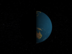
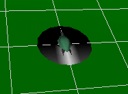
SCALE x y z : the default ratio of scale is 1 1 1. The x, y, and z are float point numbers and they ignore the number sign (positive or negative). Value 0 to x or y or z will lose its dimension. For example,
SCALE 1 0 1 BALL will create a face of a circle (a disc) as shown in the image below.
You can also use the following commands to change one dimension only:
SCALEX or SCALEWIDTH or SCALEW : change the scale of x dimension.
SCALEY or SCALEHEIGHT or SCALEH : change the scale of y dimension.
SCALEZ or SCALEDEPTH or SCALED : change the scale of z dimension.
Note: This scale series commands will affect all objects when creating in 3D space.
Logo variables
A variable is the name of location that contains a value. In the random-access machine each memory location has an integer address. Since it would be hard to remember the address of each location containing a value used by a program, computer scientists have found ways of given locations symbolic names. Once a variable has a name, we can use and manipulate it. Variables are given names which are strings of letters, hence size could be the name of a variable. When we wish to use the value of a variable in a computation, we refer to it as :size. Note the use of the colon before the name of the variable. For example, if size has been given a value, then we can say FD :size and logo will move forward by a number of units which is the value of the variable size.
There are several ways to give a value to a variable. An explicit way to do this is described below. An implicit way will be seen when we introduce procedures. A variable can be given a value with the make command, as shown below.
MAKE "size 60
This command gives size the value 60. Note that in this case we have used "size, not :size. The reason is that :size is the value of the variable size, while "size is its name. We say that "size is the quoted name of size. Logo tries to evaluate words as it reads them because some words are the names of procedures. We quote words to tell Logo they should not be evaluated. The MAKE command gives a value to a variable even if it has not yet been used in a program. In this way Logo differs markedly from Pascal. In Pascal a variable must first be given a type (declared) such as integer, real, or character, before it can be used. In Logo variables do not have types nor do they have to be declared before being used.
As a digression, consider the command PRINT. It is given one argument (parameter) and it prints the value of the argument in the interactive message text area. Thus, the command PRINT 50 will print the integer 50. We introduce this command so that we can demonstrate another use of quoted names.
Since quotation before a word means it should not be evaluated, the command PRINT "hello should print the word hello in the command window. Does it?
Now let's give the variable my_movie a value which is the name of a movie. Try executing the following commands.
MAKE "my_movie "Spy_Kids PRINT :my_movie
Note that we quote the name of the variable my_movie in the MAKE command but use the colon version to obtain its value. Spy_Kids is quoted so it is recognized as string and not a variable.
There are more variable operation commands such as LOCAL, LOCALMAKE, NAME, and ERASENAME etc. Please refer to Command Library for more information.
Mathemtical operations
Logo provides the usual arithmetic operations of addition, subtraction, multiplication and division, denoted by the symbols +, -, *, /. Each of these operations produces a result. If you don't do something with the result, Logo will complain. With the print command the result of an arithmetic operation can be used and printed in the interactive message text area. Try the following commands:
MAKE "size 81/9 PRINT 2*3 PRINT :size - 4
Other useful commands are SQRT, which takes one non-negative argument and returns its square root, POWER, which takes two arguments (parameters), call them a and b, and outputs a to the b power, and much more such as SIN, COS, and LOG etc. Try out these ideas with the following commands:
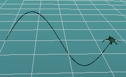
CM ; set centimeter
PD ; pendown, start recording turtle track
MAKE "degree 0 ; define variable degree with value 0
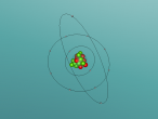
REPEAT 360 [SETXYZ :degree 100 * SIN :degree 0 MAKE "degree :degree+1]
PU ; penup, end of recording turtle track
The figure it produces is shown below.
Arithmetic operators have precedences that determine the order with which they are evaluated. Note that PRINT 60 * SQRT 2 and PRINT SQRT 2 * 60 produce different answers. Here the * operator has precedence over the SQRT operator. Thus, * will be done before SQRT if there is a choice, as there is in the second case. For this reason the first statement prints the value of 60 times the square root of 2 whereas second prints the square root of 120.
Sometimes it is fun to have the outcome of a computation be unpredictable. Logo provides the RANDOM command to generate a random number. RANDOM has one argument (parameter) and produces an integer value chosen uniformly at random between 0 and the value of its argument minus 1. Thus, if you want a random angle between 0 and 359 degrees, you could use the command RANDOM 360 to produce it. Bear in mind that Logo will complain unless you do something with the result, such as print it. Try PRINT RANDOM 360 several times in the command input text field and see what it produces. For a little more fun, try
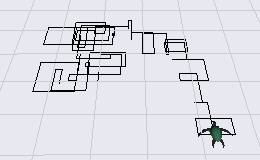
CM
CS PD REPEAT 100 [FD RANDOM 100 RT 90] PU
CS PD REPEAT 100 [FD 50 RT RANDOM 360] PU
The first repeat produces a drawing such as that shown below. What does the second do?
There are more arithmetic operation commands in Command Library page.
Other commands
VRMath's Logo is a derivative of TurtleTracks (broken link), which is implemented based on UCBLogo. Most other commands will be the same as the above two Logo languages. VRMath also references other versions of Logo such as MSWLogo and MicroWorlds etc. for some commands and their interface design.
Some commonly used commands are:
HOME : reset turtle's position to (0,0,0), and orientation to heading north.
CLEAN : erase all objects created in 3D space.
CLEARSCREEN or CS : this command does both HOME and CLEAN.UNDO : undo the last object created.
REDO : redo the last undo action.
PENERASE or PE : undo one turtle track for PD object.PRINT : This command prints the result or content of its parameter in the interactive message text area. For example, PRINT SQRT 100 will show the result 10. This is helpful when debugging the commands or procedures.
REPEAT : This command has two parameters (arguments). The first is the repeat times. The second is a LogoList enclosed by "[]" with the commands in it. For example, REPEAT 4 [FD 1 RT 90] will ask the turtle move a square.
There are much more commands that you can find in the Command Library such as the flow control language set, input/output command set, and commands for words and lists manipulations etc. They are also very important for the development of higher level thinking in logic and 3D geometry.
Logo procedure
Procedures provide a way to encapsulate a collection of commands. Once a procedure has been created, it can be used just the way a built in command is used. The meaning of a procedure is the meaning of its individual commands.
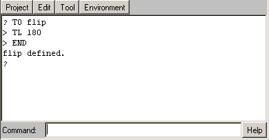
A procedure without parameters (arguments) has the word TO (a reserved word) and the name of the procedure on the first line. (Reserved words in Logo cannot be used as variables and have a well-defined meaning and use.) It has the reserved word END on the last line. The procedure shown below encapsulates the next to the last set of instructions shown above. After writing it with the editor, invoke the procedure flip by typing it in the command input text field.
TO flip
TL 180
END
In VRMath, you can create the flip procedure in the command input text field by typing in line by line. The process is shown in the figure below.
Or you can use a Procedure Editor in Tool menu or by using EDIT "flip command to do so.
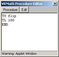
After your writing is finished, please execute to define the flip procedure.
If your procedure is correct, you will see the message "flip defined" in interactive message text area. By now, you have created a procedure named flip. Flip has become a command or primitive with no parameter. You can now invoke flip command by typing in flip in command input text field and you will see the turtle flips.
Procedures can contain not only built in commands, they can also contain other procedures. Procedures can also have parameters, which will make procedures more powerful. Following the procedure name on the first line any number of variables can be specified in the colon format, as illustrated below:
TO square :size
REPEAT 4 [FD :size RT 90]
END
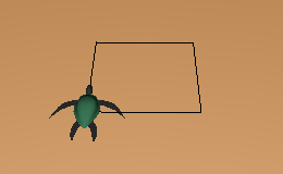
This procedure creates a square. To use it, try the following commands:
METER PD SQUARE 1 PU
When a procedure invokes a copy of itself, it said to be recursive. The meaning of recursive procedures is obtained in exactly the same way as regular procedural invocation, namely, via the copy rule. An example of a recursive procedure is given below.
TO tree :size
IF :size < 5 [STOP]
FD :size
LT 45 tree :size*.7
RT 90 tree :size*.7
LT 45
JB :size
END
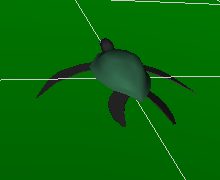
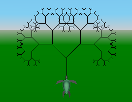
After tree procedure is defined (execute it!), try the following commands will get the figure below.
CM ; use centimeter
RU 90 ; turn the turtle's head towards sky
PD ; pen down
tree 80 ; draw a recursive tree
PU ; pen up
BEWARE. Recursive procedures should have a exit condition. For example, in the tree procedure:
IF :size < 5 [STOP]
otherwise, some recursive may run indefinitely. If this happens, you will have to terminate the execution thread by using Interrupt in Environment menu. And of course, you may want to modify your procedures. You can do so by using EDIT command such as
EDIT "tree
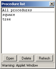
or use Procedure List in Tool menu (Open into editor...) to open multiple procedures in one editor or delete procedures.
Project management
In VRMath, users can create their own projects, and save them over the Internet. And of course, projects can be retrieved anytime when users are using VRMath. Projects can also be made public by their authors, so other users can open those public projects and study them. Public projects will not be changed except the authors themselves. However, every user can save another copy of the public project to be their own.
A project contains the following information:
- author
- title
- description
- public status
- create date and time
- last edit date and time
- procedures
Note: The current implementation of VRMath does not include the 3D content you created in your project. It is recommended that you write procedures to keep all 3D content easy to be recreated. At the moment, you can only export the 3D content to VRML.
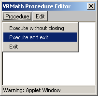
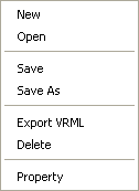
To manage projects, we mainly go through the Project menu with those functions in the figure below.
Before you use those functions, you have to register in VRMath forum to become a user of VRMath. This is free to public. However, you have to agree the VRMath forum - Registration Agreement Terms to register.
After you have registered, please login to VRMath forum when you are using VRMath. If you don't login, and you try to use any function in project menu, you will get a message like the figure below.
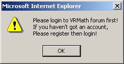
Only if you have registered and login, you can use those project management functions.
For more information about project menu functions, please refer to Project menu in Programming Interface page.
Logo links
This tutorial page has described most distinctive features of VRMath. However, it is also helpful for learning more VRMath Logo from other Logo resources. Below are some important links for Logo.
- The Logo Foundation by the MIT Media Lab and by MaMaMedia
- EuroLogo, the European Society for LOGO.
- Logo Links for School of Abraham by Dale R. Reed
- Logo Tree Project by Elica
- Turtle Tracks Project by Daniel Azuma
- Brian Harvey, professor of computer science at UC Berkeley, is one of the chief developers and proponents of the Logo language. His implementation of Logo, Berkeley Logo, is free and available for Unix, Macintosh and Windows platforms.
- Based on Berkeley Logo, MSWLogo is a commonly-used freeware implementation by George Mills. It runs only under Microsoft Windows.
- Yoyo is a Java-based project at MIT implementing some variations on Logo.
- MicroWorlds from LCSI
- Star Logo from MIT
- 89101 reads