more gears, fast
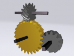
I updated the involute (curved teeth), helical gear generation procedure to use Extrusion rather than IndexedFaceSets. Extrusion automatically supports the back and front faces of the gears, and a smooth appearance by producing a mesh with points shared by triangles. So the logo code could be streamlined and therefore is now much faster generating gears.
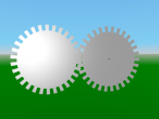
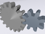
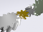
However, since extrusions with teeth or other concave corners have some issues with current x3dom, the maximum number of teeth currently is 14. Here is a nice gears mesh with four such helical gears.
The main involute gear profile function remained unchanged but 3d gears are produced as extrusions. Here is the complete logo code for above:
ERALL ; involute: draw involute ; rb: base radius ; limit: max. generating angle ; steps: number of segments on involute to draw ; returns list of positions: top is first TO involute :rb :limit :steps LOCALMAKE "start POS LOCALMAKE "i 0 LOCALMAKE "step 0.5 * :limit / :steps LOCALMAKE "coords [] PUSH "coords POS PU REPEAT ABS(:steps) [ ;push "coords :start MAKE "i :i + :step ;move along circle LT :step FD 2 * :rb * SIN :step ;find tangent RT 180 - :step ;unroll string FD 2 * :i * :deg2rad * :rb ;make "start pos ;record position PUSH "coords POS BACK 2 * :i * :deg2rad * :rb ;turn forward LT 180 ] SETPOS :start OUTPUT :coords END ; gearinvolute: draw involute side of gear tooth ; rb: base radius ; PA: pressure angle ; P: diametral pitch ; steps: number of subdivisions ; returns list of position from landing to base TO gearinvolute :rb :PA :P :steps LOCALMAKE "a 1 / :P LOCALMAKE "ro ( :rb / COS :PA ) + :a ;calculate generating angle for top of tooth ;(needs drawing) LOCALMAKE "l2 :ro ^ 2 - :rb ^ 2 LOCALMAKE "limit ( SQRT :l2 ) / :rb LOCALMAKE "coords involute :rb (:limit / :deg2rad) :steps OUTPUT :coords END ; geartooth: draw one full tooth ; rp: radius of pitch circle ; PA: pressure angle ; P: diametral pitch ; hdelta: half angular base width (expected) ; segments: number of subdivisions on each side ; returns list of positions from root to landing to root TO geartooth :rp :PA :P :hdelta :segments LOCALMAKE "rb :rp * COS :PA LOCALMAKE "clr (2.157 - 2) / :P ;coarser 20P LOCALMAKE "ddif (1/:P + :clr) - (:rp - :rb) LOCALMAKE "coords [] PUSH "coords POS ; record straight edge RT 90 FD :ddif PUSH "coords POS LT 90 ; save position LOCALMAKE "base POS LOCALMAKE "head HEADING ; record side MAKE "coords SENTENCE ( gearinvolute :rb :PA :P :segments ) :coords ;record with negative step LOCALMAKE "top POS SETPOS :base SETHEADING :head ;turn and move to other side of tooth ;half angular base width LT :hdelta FD 2 * :rb * ( SIN ( :hdelta ) ) LT :delta / 2 ;save pos MAKE "base POS MAKE "head HEADING ;draw other side ;prepend reverse MAKE "coords SENTENCE REVERSE ( gearinvolute :rb :PA :P :segments * -1 ) :coords ;return to base SETPOS :base SETHEADING :head ;record straight edge LT 90 FD :ddif PUSH "coords POS RT 90 OUTPUT :coords END ; gear: draw involute gear ; rp: radius at pitch circle ; PA: pressure angle ; P: number of teeth normalized by pitch diameter ; segments: subdivions on each involute side of each tooth ; returns list of positions TO gear :rp :PA :P :segments LOCALMAKE "cpitch :PI / :P LOCALMAKE "apitch (:cpitch / :rp) / :deg2rad LOCALMAKE "N :P * :rp * 2 LOCALMAKE "rb :rp * COS :PA LOCALMAKE "clr (2.157 - 2) / :P ;coarser 20P LOCALMAKE "ded (1/:P + :clr) LOCALMAKE "rr :rp - :ded ;this is the main calculation ;for angular base width delta ;(needs drawing) LOCALMAKE "alpha ( TAN :prA ) / :deg2rad LOCALMAKE "beta :alpha - :prA LOCALMAKE "delta ( 0.5 * :apitch ) + ( 2 * :beta ) LOCALMAKE "coords [] ; move from center to root PU RT 90 FD :rr LT 90 REPEAT :N [ ;tooth from root to root MAKE "coords FPUT ( geartooth :rp :PA :P :delta / 2 :segments ) :coords ;advance to root of next tooth LT (:apitch - :delta) / 2 FD 2 * :rr * SIN ((:apitch - :delta) / 2) LT (:apitch - :delta) / 2 ] ;close up ;make "coords fput pos :coords LT 90 FD :rr RT 90 OUTPUT :coords END ; helicalGear: create a helical gear as an extrusion ; with its internal center ; at the position and orientation of the turtle ; PR pitch radius ; PA pressure angle ; P pitch ; iS number of segments defining involute ; W depth ; HA helical angle ; fS number of segments across depth extent TO helicalGear :PR :PA :P :iS :W :HA :fS ;save turtle LOCALMAKE "tpos POS LOCALMAKE "tori HEADING ; setup turtle for generating gear ; needs this starting configuration due to extrusion HOME RU 90 ; produce gear in xz plane at origin LOCALMAKE "gear3d gearExtrusionY (gear :PR :PA :P :iS) :W :HA :PR :fS ; put at turtle position and orientation SET :gear3d "rotation :tori SET :gear3d "translation :tpos SETPOS :tpos SETHEADING :tori ;return object for further manipulation OUTPUT :gear3d END TO gearExtrusionY :positions :width :helix :r :fsegments ;positions are expected in the xy plane EXTRUSION LOCALMAKE "extrusion WORD OBJECT "_extrusion ;reset any initial rotation SET OBJECT "rotation [1 0 0 0] ;make cross-section ; just xy and close by repeating last point LOCALMAKE "cs flatten :positions SET :extrusion "crossSection flattenxy FPUT (LAST :cs) :cs ;set :extrusion "crossSection flattenxy reverse :cs ; make spine, scale, orientation per segment ; spine centered at 0 LOCALMAKE "sp [] LOCALMAKE "sc [] LOCALMAKE "rot [] LOCALMAKE "rothA (TAN :helix) * :width / :r FOR [s 0 :fsegments] [ ; make spine ; needs to be in Y or X direction, use Y QUEUE "sp ( LIST 0 (:s * :width/:fsegments - :width/2) 0 ) ; make scale, constant QUEUE "sc [1 1 1] ;make orientation for helix QUEUE "rot ( LIST 0 1 0 :s * :rothA / :fsegments ) ] SET :extrusion "spine flatten :sp SET :extrusion "orientation flatten :rot SET :extrusion "scale flatten :sc SET :extrusion "creaseAngle 1.57 SET :extrusion "endCap TRUE SET :extrusion "beginCap TRUE OUTPUT OBJECT END TO combxy :xyz1 :xyz2 OUTPUT SENTENCE BL :xyz1 :xyz2 END TO flattenxy :xyzpos OUTPUT BL REDUCE "combxy :xyzpos END TO flatten :listoflists OUTPUT REDUCE "sentence :listoflists END ;involute (for gears) ;comprehensive guide ;http://bostongear.com/pdf/gear_theory.pdf RESET CLEARSCREEN SETBACKGROUND 34 ;pointlight MAKE "PI 4 * RADARCTAN(1) MAKE "deg2rad :PI / 180 MAKE "prA 20 ; pressure angle MAKE "piR 0.5 ; pitch radius 1 MAKE "piR2 0.25; pitch radius 2 MAKE "pitch 14 ; pitch for all gears MAKE "isegments 6 ; involute segments MAKE "facesegments 4 ; number of cross-sections MAKE "hAngle 45 ; helical angle MAKE "depth 0.2 ; gear depth ;ru 90 ;make first gear horizontally, at origin TRANSFORM MAKE "g1spin OBJECT SETPARENT :g1spin SETMATERIAL 3 33 MAKE "g1 helicalGear :piR :prA :pitch :isegments :depth :hAngle :facesegments ;use inner trafo for initial rotation MAKE "beta (TAN :prA) - (:prA * :deg2rad) SET :g1 "rotation (LIST 0 1 0 :beta) SETPARENT "root ;make second gear horizontally, at origin TRANSFORM MAKE "g2spin OBJECT SETPARENT :g2spin SETMATERIAL 3 18 MAKE "g2 helicalGear :piR2 :prA :pitch :isegments :depth -:hAngle :facesegments ;use inner trafo for initial rotation SET :g2 "rotation (LIST 0 1 0 :PI/:pitch/:piR2/2 + :beta) SETPARENT "root ;make third gear horizontally, at origin TRANSFORM MAKE "g3pos OBJECT SETPARENT :g3pos TRANSFORM MAKE "g3spin OBJECT SETPARENT :g3spin SETMATERIAL 3 26 MAKE "g3 helicalGear :piR2 :prA :pitch :isegments :depth -:hAngle :facesegments ;use inner trafo for initial rotation SET :g3 "rotation (LIST 0 1 0 :PI/:pitch/:piR2/2 + :beta) SETPARENT "root ;make fourth gear horizontally, at origin TRANSFORM MAKE "g4pos OBJECT SETPARENT :g4pos TRANSFORM MAKE "g4spin OBJECT SETPARENT :g4spin SETMATERIAL 3 30 MAKE "g4 helicalGear :piR :prA :pitch :isegments :depth :hAngle :facesegments ;use inner trafo for initial rotation SET :g4 "rotation (LIST 0 1 0 :PI/:pitch/:piR/2 + :beta) SETPARENT "root ; place second gear RT 90 FD :piR + :piR2 SET :g2spin "translation POS ; rotate and place third gear FD 2*:piR2 SET :g3pos "rotation [1 0 0 -1.57] SET :g3pos "translation POS ; rotate and place fourth gear FD :piR2 + :piR SET :g4pos "rotation [1 0 0 -1.57] SET :g4pos "translation POS ;spin MAKE "period1 10 SPIN :g1spin "lt :period1 SPIN :g2spin "rt :period1 * :piR2/:piR SPIN :g3spin "rt :period1 * :piR2/:piR SPIN :g4spin "lt :period1 PU SHOWALL
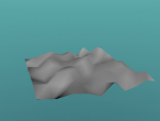
And here is mesh with pitch 42 which requires a fix to x3dom which can be dynamically applied, see below.
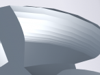
If the front and back face of the large gears do not show, please use this user script with Greasemonkey (install here):
Reload the page after enabling the user script.
- aplesch's blog
- Login or register to post comments
- 4551 reads
Comments
ear clipping
Hope x3dom can pull this request soon. I am aware of the concave polygon issue for a long time and very glad to see it is fixed by your earclipping script.
The involute gear has much smoother gear teeth than my 4-circle gears. Thanks for enriching the contents of VRMath2.
I noticed that Blender and MeshLab cannot not import extrusion so that could be a down side for extrusion gears. The IndexedFaceSet gears will be still very useful... and I need to add script to remove the duplicate coordinates too.
merged
My PR was merged. Since the PR was a bit premature though functional, I submitted a second PR with cleaned up code and some other improvements. It is available as a Greasemonkey user script as well, linked from the PR, and above.
It unfortunate that Blender and Meshlab cannot import extrusion. I guess they do not have a native corresponding object or concept. Since x3dom in effect produces an IndexedFaceSet from the the Extrusion it may be possible to come up with a converter.
The facet optimizing function should pretty much do what you need.
x3dom updated
VRMath2 is now using the x3dom with #576, therefore, the gears above are rendering correctly with both caps.
I have also tested your improved EarClipping in https://github.com/x3dom/x3dom/pull/577 and left a comment there.
remove duplicate coordinates
I have some options to do so. I can follow your codes after the coordinates of the indexedfaceset was created, or I can check for duplicate coordinates during the creation of indexedfactset (PENDOWN). I am thinking of the later. It may slow down the creation because of checking, but once checked it actually saved time because I only need to update the indicies and not the coordinate points and colors.
Do you know the internal structure of the extrusion in x3dom? There are probably some converters (at least this commercial one http://www.okino.com/conv/imp_vrml.htm) but It will be good if there is an api in x3dom to call.