


Gear 2D Prototype


Following the circle involute blog, I thought about creating a gear procedure for easy creation of different gears. The method used is quite differnt to the involute idea but the turtle geometry way of thinking and doing the gears. This prototype procedure utilised a simple regular poygon formula (repeat :sides [ fd 1 rt 360/:sides ]) and some built-in commands such as TOWARD and SETHEADING to rotate the turtle and get the directions needed.
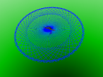
The example below shows two rotating gears each with 30 teeth.
Below is the Logo program to create the above 3D world.
This is a first attempt to create a gear procedure. The tip of gear tooth will need some refinement. I will continue to make the refinement and the next version will be a 3D version of gear.. and in fact I have got other ideas to refine it...
In case you need the files, here they are: gear2d_proto.x3d gear2d_proto.logo
- Andy's blog
- Login or register to post comments
- 8733 reads


Comments
More about gears
I found that my initial gear prototype is much too simple... basically it is maths and geometry. But to put it into realworld, there are more about gears need to be understood so a proper gear can be modelled.
In previous comment, I added a link to on online gear tool, in which I found about "Contact angle". With some more googling I found some fundamental knowledge about gears, at
http://www.xtek.com/pdf/wp-gear-terminology.pdf
When programming, I also thought about the size of gear, then I found this interesting dicussion about it at http://www.thenakedscientists.com/forum/index.php?topic=42746.0
The Boston Gear comapny even has a gear theory document online here at http://www.bostongear.com/pdf/gear_theory.pdf
I have not yet writen my 3D Gear procedure in Logo, but I am already thinking about the potential to make it a learning project for school or engineering students. Also if x3d can be converted to STL or PLY then the gears can be printed by 3D printers.... hm.. more research to do..
limitations
After some research, I came across this online tool and found it is more useful to fix tooth size so can have different sized gears for different gear ratio.
https://woodgears.ca/gear_cutting/template.html
nice
Nice gear prototype. For curved sides, it will be necessary, I think, to find out how wide the base of a tooth is in relation to its width at the center. At the center the width of a tooth is half of the spacing between two teeth. The other half is for the gap. At the base the width of the tooth is wider due its curved shape. Since I could not find a formula for the angular width of a tooth at the base, I may need to sit down and do some geometry which is exciting. It will depend on the contact angle, aka pressure angle, and on the dedendum which can be determined.