3d involute gears

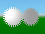
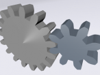
As an update to the 2d involute (curved teeth) gears, I modified the program to produce 3d (extruded) gears. This required a change in drawing tactics.
First, the turtle moves along the gear without drawing anything but only recording its position into a growing list of coordinates. This actually simplified some aspects of drawing the gear since less temporary saving of positions was required. Second, the recorded path is used to generate faces away from the path going segment by segment. The reduce command was convenient for this procedure since it supplies two neighbouring values of a list. Finally, nested transforms are used to adjust the initial rotation of the gears so they mesh together (inner transform) and to spin the adjusted gears (outer transform). To avoid any intersection of the gears, the second gear is moved a small bit farther away from the first gear than strictly necessary. I believe, real small gears tend to require "undercuts" to avoid the same issue.
[Next, I would like to fill in the front and back. Due to the curved shape of the teeth, this will require some more sophisticated face generation.]
Update: front and back are now closed, and some general changes.
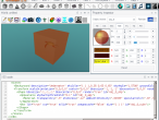
Here is the updated, commented logo program:
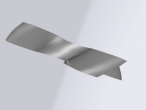
Here is an example with pitch 32 (more teeth) and a pressure angle of 20. It shows the limitations of the skinny triangle approach.
And here the same gears with improved front and back mesh:
Only a few changes were necessary. First, I changed the data structure of the gear profile from a flat list of positions to positions grouped by tooth:
Then it was a matter of adjusting the front and back plate drawing procedure to draw a polygon per tooth and then a large circular polygon for the center:
Finally, a flattening transformation of the gear profile data structure is required to be able to continue to use the fence procedure:
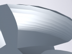
Here is a picture of the new front and back mesh which x3dom generates for the provided polygons:
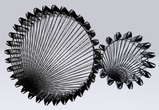
Fig. 1: Triangulation front and back plate polygons
- aplesch's blog
- Login or register to post comments
- 30919 reads













Comments
PointLight
Noticed that you also used a PointLight. I think that X3DOM has implemented well the lights. There is an example pointlight_test.vrm in the Example vrm folder (open from the 3D world window in VRMath2 Editor). You can select the PointLight from the Object Tree window, then manipulate from the TE or OS tabs in the Property Inspector window.
New blog
It is great to see this 3D version in a new blog. Thanks for the continuing contribution. Your involute gear demonstrated many powerful uses of programming driven 3D modelling. There are new technologies such as 3D scanning to create 3D models with complex face, which Logo may not be able to do. But there are also many things Logo can do better, such as the gear project you started, I think that the gears mathematically created from your Logo program would be better than a scanned one.
I found that you have mastered most Logo commands. The LIST (array) manipulation in Logo is quite easy. Some special characteristics about Logo are differnt to other programming. For example, SIN (2) is the same as SIN 2. The maths function (command) needs an input. Unless there are some operations required, the parenthese are not needed.
OUTPUT THING "coords is also the same as OUTPUT :coords. The variable name and string (WORD) in Logo can be confusing to many who are new to Logo.
I also found that you have created an extrusion procedure, which is so brilliant. However, I have planned to include EXTRUSION into my Logo 3D primitives. This means that when I have implement EXTRUSION as a native command, you cannot overwrite it or have a procedure that has the same name as a built-in native command. So could you please change the extrusion procedure name to a different name so your program will still run after I included EXTRUSION?
There is a trick in X3DOM's IndexedFaceSet. By default it is set to convex=true, but even it is changed to false for the gears, it will still not render the gear correctly. I am not sure if that is a bug or implementation decision of X3DOM. The way I create the crosssection of gear face is to start from the center of the gear then walk (SETPOS) through the gear coordinates. This way, X3DOM seems to render the gear face I want.
pasted object not in blog
I copy and paste the front plate to the back, and it works fine in the world viewer after I run the logo program. However, after exporting the x3d and including the scene here in the blog the back face does not show up although it is definitely there as a "USE" shape in the x3d.
I think, the problem may be that the USE object comes in the x3d file before the DEF shape. Running the Logo dynamically updates the DOM, eg. there the scene has the DEF shape before the USE shape. In contrast, when x3dom parses the x3d file, it does not yet know about the DEF shape when it encounters the USE shape and cannot render it.
Is there a way to put the use DEF object before the USE object in the x3d export ?
-Andreas
PS: it looks like now paste does update the latest object and the object command now can refer to the pasted object. Thanks for fixing.
first def, then use for inline
I could confirm that the order of def and use objects is the issue by manually editing the x3d to switch the use/def for the blue gear to def/use:
https://vrmath2.net/content/ap-scenes
shows the result which now has the back plate for the blue gear.
I repeated the posts in the forum fir further discussion at some point.
thanks
Great comments.
I found that
does not work when mylist is a list rather than a string or number. output thing "mylist works.
I ran into a couple of other limitations of the logo interpreter (see forum) but overall it works quite well.
I renamed the extrude procedure to gear3d which is a better name now anyway because it also does the front and back of the gear.
convex=false unfortunately does not work in x3dom. It is a bug with an issue but would probably require a better triangulation method.
I used the skinny triangle approach instead which produces produces some zero area triangles but x3dom does not seem to care.
For me on firefox the logo editor and the x3d export stopped working ?
Thanks again for a great environment.
x3d by itself is also a great learning tool. So I think it may be worthwhile to think about a similar environment as an x3d editor without logo. It may mostly require removing functionality and an ability to edit the x3d. just a thought
-Andreas
Firefox 41.0.2 seems ok
I just tried Firefox on both my MBP and PC. VRMath2 Editor seems to be running well in Firefox version 41.0.2 (was updated). In this version of Firefox, I did find its WebGL performance is slower than in Chrome. The Publish dialog in VRMath2 Editor is also out of alignment in Firefox.
I usually use Google Chrome for VRMath2. And these days, web browsers update themselves in a much shorter time span. Sometime I found small problems such as HTML element alignment issues but usually when updated the problem is resolved. I hope the Firefox problem you encountered can be fixed with the latest version of Firefox.
I am also aware that the Logo Editor did not work well on Mobile devices such as iPad. It seems that my old version of KendoUI and new version of CodeMirror did not work together well for iOS devices. Mobile Safari also has scroll problem for iFrame, which I used for my Logo Guide window. It is very difficult to resolve these issues.
editor
I have to use firefox 38.3 and it it worked well in the past. But something happened and now I cannot typwe in the editor anymore. Each keystroke gets repeated many times along woth previously entered characters. Also the line numbers are offset from the grey left margin into the white text area.
Try old codemirror
I suspect this could be due to my recent update of CodeMirror from 3.21 to 5.7. However, I updated for some weeks already. Do you always use Firefox 38.3 and throughout all the Logo programs you wrote?
Try this url https://vrmath2.net/VRM2/?cm=old
It will load older version of CM. Thanks for testing.
codemirror
https://vrmath2.net/VRM2/?cm=old works, eg. let's me use the editor !
I used different browsers on windows and linux, and probably have used 38.3 even after the code mirror update. Perhaps something was cached ?
Andreas
experienced before
I did experience similar situation before but since browsers updated, I can't reproduce the editor problem. I have made sure that both the server and my computer cache are cleared. When testing I also use private mode in browser so no extensions could interfere.
Sometimes the browsers have minor updates that can create or solve problems. For example, previous Chrome has mouseover (show title or tip) problem, but it was gone in current version.