Extrusion Star

This is another test of using EXTRUSION object, perhaps a much easier test than previously on gears. In one of the Challenges, I was hoping some one can use simple geometry of pentagon to create a 3D star. It turned out EXTRUSION can achieve this quite easily.
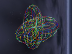
Let's see the final product here first, and I will explain how this was done.
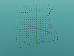
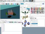
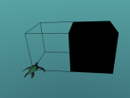
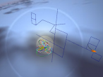
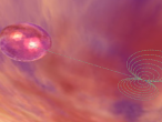
The star is pentagonal, so I firstly utilised the regular polygon idea and get the turtle to walk to the pentagon's vertices on the X-Z plane, and collect the X coordinates and Z coordinates for crossSection later. There are two pentagons to collect coordinates as shown in the below pictures.
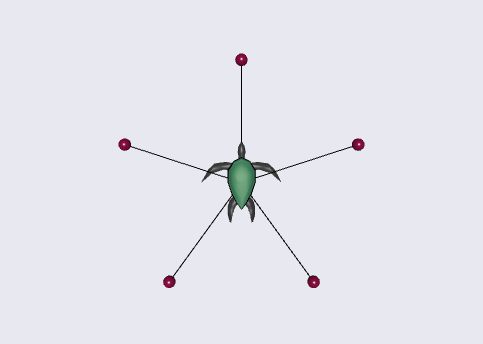
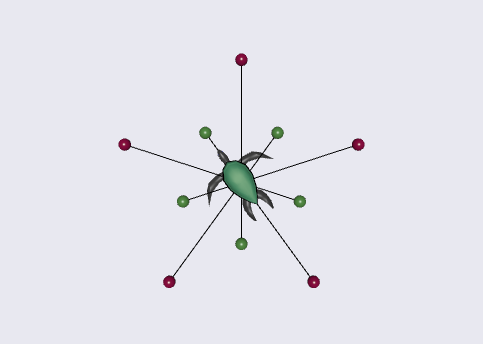
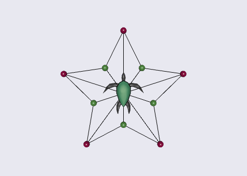
The collected crossSection coordinates (XCOR, ZCOR) have to be sequenced counter clockwise as the default ccw field is set as true. So in the Logo program I used LT (left turn) to achieve this (can be seen in the middle picture above). The convex field of EXTRUSION (and INDEXFACESET) does not work as I expected, so I have to in fact collect the crossSection from 0, 0, then red 1, green 1, and so on, then back to red 1 and then 0, 0 again to make this concave 2D star crossSection work.
The full Logo program is shown below with some comments.
EXTRUSION still has some strange behavious but for normal X-Z plane crossSection and spine along Y axis it seems to work well.
- Andy's blog
- Login or register to post comments
- 9515 reads

























Comments
convex
Great to see extrusion put to good use. I found that some caps for extrusions do not work because of how earclipping is implemented in x3dom. I am trying to fix some things there.
Thanks
Looking forward to see the refining of x3dom. Your work is much appreciated.
concave fix
I submitted a preliminary fix for concave cross-sections as a pull request here:
https://github.com/x3dom/x3dom/pull/576
You should be able to try out the fix with a greasemonkey user script as described in this comment:
https://github.com/x3dom/x3dom/pull/576#issuecomment-155187976
If it works, you could start to include the fixed Earclipping.js from here:
It worked for my gear extrusions and other examples. Give it a try.
simple test it works
I did a simple test with the Logo codes below:
Without your fix, from current https://vrmath2.net/VRM2, I get the result below:
After running the codes, need to set convex to false (in OS tab), then refresh the 3D window. This is another bug in x3dom. Changing ccw or convex field will not redraw.
With your fix, I temperarily applied to https://vrmath2.net/VRM2/?cm=old, will get the result below.
Your fix is working and producing the result of concave polygon as expected.
However, I am wondering now with your fix, there seems no need to use ccw or convex=true. Another interesting situation if the IndexedFaceSet or crossSection is a complex shape (lines cross over), the result is probably uncertain, but in the case below, with or without the fix, it seems to get the same results. (Only in early plugins such as Cortona will produce a star).
ccw
Thanks for testing this a bit. This is good news.
The Earclipping code did and does not deal with the ccw and convex fields. My understanding is that the ccw field should just affect how lighting is applied (where the normal of triangle points) but not the generated mesh geometry (other than the winding order of the triangle points).
The convex field needs to be set to false for concave geometries although I am unsure what the spec says for convex=true with concave geometries. In this case it might still allow concave rendering but not require it.
I think it is intended as a hint for faster performance by allowing convex meshing which is trivial and does not require earclipping.
default convex to false
Yes.. I seem to remember that ccw will affact which side of polygon to be rendered when solid is true. Of course the earclipping is mainly for concave polygon only . If convex defaults to true is only for performance issue then I should have convex defaults to false in my VRMath2 Editor as concave rendering with earclipping can fit for both convex and concave polygons so is more friendly to my potential users (say school students).
The EarClipping document (http://www.geometrictools.com/Documentation/TriangulationByEarClipping.pdf) and the earcut js library (https://github.com/mapbox/earcut) with the optimised ear slicing algorithm are amazing. The mathematical ideas about convex and concave polygons start in Primary schools, and they are not difficult to explain or create (draw or cut). Then when young children start to create on computer, say using tools similiar to the Extrusion in CAD Component Editor (http://examples.x3dom.org/editor/component_editor/), they may start to learn that there are more mathematics behind the computer representation of concave polygon. I think the value is great if my VRMath2 can involve learners in projects and enable them to make connections between mathematics, science, technology and engineering, while learning about them.